
Marine HVAC terminal unit
UAT Marine Cabin Units by Sedina-HVAC
Enhance onboard comfort for passengers and crew
The UAT Cabin Unit is a compact, ceiling-mounted air distribution and airflow-control unit for ship cabins and offshore accommodation spaces such as crew, staff and passenger cabins. It receives prepared supply air from the vessel’s central HVAC system, regulates or distributes the required air volume and delivers it to the occupied space through a compatible UAD Diffuser.
50–500 m³/hdepending on the model
Fixed or adjustableAirflow control
Single or dual ductSupply-air configuration
UAT + UAD SYSTEM
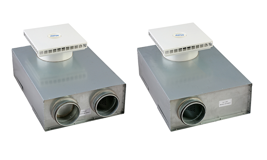
Available options
Available configuration options
The unit is installed in the available space between the suspended ceiling and the deck. Its low-profile arrangement supports coordination with ductwork, ceiling structures and other technical services where installation space is restricted.
01
Airflow control
Fixed or adjustable
02
Reheating
No reheat, electric reheat or hot-water/water-glycol reheat.
03
Duct arrangement
Single-duct or dual-duct supply-air configuration.
04
Materials and surface finish
Galvanised sheet steel as standard, with powder-coated, AISI 304 and AISI 316L options.
05
Compatible diffuser
UAD Diffuser Sizes: DN200 for UAT-1 and UAT-2 units, and DN250 for UAT-3 units.
06
Optional accessories
TR-001X wall-mounted room thermostat and zone control valves for water-heating systems.
Applications
Applications on ships and offshore installations
UAT Marine Cabin Units distribute conditioned supply air in accommodation and interior spaces where compact installation and local airflow control are required.
Sedina UAT Marine Cabin Units are designed for installation in marine and offshore spaces, including:
- technical rooms requiring continuous air exchange and ventilation.
- general accommodation areas and corridors;
- galleys and shipboard offices;
- interior technical or service rooms where the selected configuration is suitable;
- offshore living quarters and accommodation modules;
- newbuilding, conversion and retrofit projects, subject to dimensional and interface verification.
For each application, the cabin unit should be selected as part of the overall HVAC system design. Required airflow, supply-air temperature, duct pressure, room heat load, reheat demand, installation access and applicable fire or marine-equipment approval requirements should be defined before model selection.
B-15
Fire integrity
B-15 Fire Integrity and MED Certification
Sedina UAT Cabin Units are approved for use within the certified B-15 ceiling arrangement in accordance with the applicable MED type-approval requirements.
The B-15 classification applies to the complete tested assembly. It confirms that the assembly meets the applicable fire-integrity and thermal-insulation requirements when installed in the approved configuration and in accordance with the approved construction, materials, mounting arrangement and installation details.
Technical overview
Key UAT data
| Airflow range | 50–500 m³/h depending on the model |
|---|---|
| Electric heating | Up to 3600 W only where confirmed for the relevant model |
| Water heating | Up to 2700 W only where confirmed for the relevant model and operating conditions |
| Electrical supply (reheating) | 230 V AC, 50/60 Hz |
| Standard casing materials | Galvanised sheet steel |
| Optional casing | AISI 304 / EN 1.4301 or AISI 316L / EN 1.4404 |
| Surface finish | Optional powder-coated finish |
| Insulation | 25mm thick mineral wool insulation with non-woven tissue |
| Diffuser sizes | DN200 for UAT-1 and UAT-2; DN250 for UAT-3 |
System principles
Design & Operation
Fixed flow
In fixed-flow UAT units, the design airflow is set during system commissioning and remains unchanged during normal operation. No airflow-adjustment device is included in the cabin unit.
Room temperature control: Where electric or water reheating is used, the airflow remains constant while the supply air is reheated within the UAT cabin unit to the temperature required to maintain the room temperature at the thermostat setpoint.
Models: UAT, UAT-E and UAT-W model families
Adjustable airflow
Adjustable UAT variants allow the supply-air volume to be regulated directly from the UAD diffuser using a control knob integrated into the diffuser, which operates the airflow-regulating mechanism inside the cabin unit.
Room temperature control: In the configuration without electric or water reheating, cabin temperature can be controlled by changing the airflow rate while the supply-air temperature remains equal to the temperature delivered by the central air-handling unit.
Models: UAT-C, UAT-CE, UAT-CW and dual-duct UAT-C2 models.
For dual-duct UAT cabin units, the control knob regulates the proportion of warm and cold supply air delivered to the cabin, providing local temperature adjustment without a separate reheating.
Electric and water-based reheating
The UAT family may be configured without local reheating or with electric, hot-water or water-glycol reheating. The correct choice depends on the vessel’s energy systems, available utilities, control philosophy, required heating output and installation interfaces.
Configuration · Heat source · Control considerations
No reheat
Prepared supply air from central HVAC
Fixed-flow: room temperature is controlled by the air handling unit
Adjustable-flow: room temperature can be controlled by varying the supply-air volume flow rate at a constant supply-air temperature.
Electric reheat
Electrical heater
Room temperature is controlled by a wall-mounted thermostat. Electric heaters are protected against overheating by safety switches with automatic and manual reset.
Hot-water reheat
Vessel hot-water system
Room temperature is controlled by a thermostat. An automatically controlled regulating valve is available for water-heating systems.
Water-glycol reheat
Water-glycol heating circuit
An automatically controlled regulating valve is available for water-heating systems. Selection and operating conditions depend on the vessel’s water-glycol system.
Single-duct and dual-duct configurations
Single duct
A single-duct marine cabin unit receives one supply-air stream from the central HVAC system. The unit distributes and, where applicable, regulates or reheats that air before delivery through the diffuser.
Dual duct
A dual-duct marine cabin unit receives two separate air streams. These are typically a warm-air stream and a cold-air stream. Room temperature is controlled by adjusting the proportion of warm and cold supply air using the control knob integrated into the UAD diffuser. The arrangement must be coordinated with the vessel’s duct layout, temperature-control strategy, available pressures and cabin control requirements.
Model range
Available UAT configurations
Choose the model suffix according to the required temperature-control arrangement:
| Configuration | UAT models | Airflow control | Reheating |
|---|---|---|---|
| Standard | UAT-1 / 2 / 3 | Fixed | None |
| Electric reheat | UAT-1E / 2E / 3E | Fixed | Electric |
| Water reheat | UAT-1W / 2W / 3W | Fixed | Hot water / water-glycol |
| Adjustable | UAT-1C / 2C / 3C | Adjustable | None |
| Adjustable + electric reheat | UAT-1CE / 2CE / 3CE | Adjustable | Electric |
| Adjustable + water reheat | UAT-1CW / 2CW / 3CW | Adjustable | Hot water / water-glycol |
| Dual duct | UAT-1C2 / 2C2 / 3C2 | Adjustable | Warm/cold supply-air control |
The UAT family supports no reheat, electric reheat and water-based reheating configurations.
Electric heater protection
Designed for safe marine operation
Electric heaters are designed to meet maximum surface temperature less than 200 °C. For power supply 230V AC, 50/60 Hz safety switches protect against overheating:
- safety switch @ 60ºC with automatic reset
- safety switch @ 85ºC with manual reset
- Polycarbonate junction box with UL94 V-0 flammability rating, IP66 and IK08 protection, for power supply connection.
Thermostat
TR-001X local temperature control
The TR-001X wall-mounted room thermostat provides local temperature control for UAT Cabin Units with electric or water reheating. Airflow adjustment at the UAD Diffuser remains separate in adjustable-flow variants.
TR-001X technical data:
- wall-mounted thermostat with ON/OFF switch;
- 10(3) A, 230 V AC; 10–30 °C range;
- 0.5–1 °C switching differential;
- ±1 °C accuracy;
- gas-filled syphon sensor;
- IP20; 83 × 83 × 38 mm.
Wiring diagrams shows the thermostat in UAT-E/UAT-CE heater control circuits; water-heating systems may use a zone valves.
Selection guide
How to select a UAT Marine Cabin Unit
1
Select the UAT size based on design airflow
Choose the unit size according to the required supply-air volume:
UAT-1: 50–200 m³/h
UAT-2: 150–350 m³/h
UAT-3: 250–500 m³/h
The selected size also determines the compatible UAD Diffuser: DN200 for UAT-1 and UAT-2, and DN250 for UAT-3.
2
Select fixed or adjustable airflow
For fixed airflow, select the standard UAT configuration. The design airflow is set during commissioning and remains unchanged during normal operation.
For adjustable airflow, select a C configuration. These models use a control knob integrated into the UAD Diffuser to operate the airflow-regulating mechanism inside the cabin unit.
3
Select the Cabin Unit configuration
Choose the model suffix according to the required temperature-control arrangement:
The UAT family supports no reheat, electric reheat and water-based reheating configurations.
4
Define material and project-specific requirements
After selecting the UAT size and functional configuration, specify the required casing material or finish: galvanised sheet steel, powder-coated finish, AISI 304 or AISI 316L. Also confirm the available supply-air conditions, electrical or hydronic interfaces and applicable certification requirements.
Need engineering support?
“Contact Sedina HVAC to request the current documentation package for the selected model.”
Frequently asked questions
UAT Marine Cabin Units FAQ
Clear answers to common design, configuration and quotation questions.
What is a marine cabin unit?
A marine cabin unit – also described as a marine HVAC cabin unit, ship cabin unit, cabin air terminal or marine air terminal device – is a terminal air-distribution unit connected to a vessel’s central HVAC system. Sedina UAT Marine Cabin Units receive prepared supply air, distribute or regulate the required air volume and deliver it to the occupied space through a compatible UAD Diffuser. Depending on the selected configuration, the cabin unit may also provide electric, hot-water or water-glycol reheating.
How does a marine cabin unit control air volume?
UAT Marine Cabin Units are available with fixed or adjustable airflow control. In adjustable C, CE, CW and C2 variants, airflow adjustment is made from the UAD Diffuser using a diffuser-mounted control knob. The knob operates the airflow-regulating mechanism inside the cabin unit, providing local air volume control. This makes the adjustable UAT a marine cabin air terminal with adjustable airflow rather than a simple diffuser. The available airflow range and operating conditions depend on the selected model.
What is the difference between fixed airflow and adjustable airflow cabin units?
A fixed airflow cabin unit is commissioned to deliver the design air volume and remains at that setting during normal operation; no airflow-adjustment device is included in the fixed-flow unit. UAT, UAT-E and UAT-W families use fixed airflow. Adjustable UAT-C, UAT-CE, UAT-CW and dual-duct UAT-C2 variants use the UAD diffuser control knob to change the delivered airflow or, in dual-duct operation, the warm/cold air proportion.
How is room temperature controlled by a UAT Cabin Unit?
The control method depends on the HVAC configuration. With a fixed-flow cabin unit and no local reheat, room temperature is controlled by the central air-handling unit. With electric or water reheat, airflow remains constant while the supply air is reheated and a room thermostat controls the heating function. With an adjustable single-duct cabin unit, room temperature can be controlled by changing the airflow rate while supply-air temperature remains equal to the central HVAC supply temperature. In a dual-duct cabin unit, the UAD diffuser control knob adjusts the proportion of warm and cold supply air delivered to the room.
What is the difference between a single-duct and dual-duct marine cabin unit?
A single-duct cabin unit receives one supply-air stream from the vessel’s central HVAC system and distributes, regulates and, where applicable, reheats that air before delivery through the diffuser. A dual-duct marine cabin unit receives two separate supply-air streams, typically from a warm air duct and a cold air duct. The dual-duct terminal controls the proportion of warm and cold supply air locally. In Sedina’s UAT-C2 models, the same diffuser-mounted control knob is used for this warm/cold supply-air control.
Can a UAT marine cabin unit include electric reheat?
Yes. UAT-E and UAT-CE configurations are electric reheat cabin units. Electric heating output is available up to 3600 W only where confirmed for the relevant model. The E and CE variants are therefore electric reheat cabin units – marine cabin units with electric reheaters. The catalogue specifies a 230 V AC, 50/60 Hz supply for reheating and over-temperature protection using a 60 °C safety switch with automatic reset and an 85 °C safety switch with manual reset. Electric heaters are designed for a maximum surface temperature below 200 °C. A TR-001X wall-mounted room thermostat is used in the documented electric-heater control circuits.
Can a UAT marine cabin unit use hot-water or water-glycol reheat?
Yes. UAT-W and UAT-CW configurations are water reheat cabin units for connection to a vessel hot-water or water-glycol heating circuit. The range can provide water-based heating output up to 2700 W only where confirmed for the relevant model and operating conditions. A room thermostat can control the heating demand, and a zone control valve is available for water-heating systems. Selection of a marine cabin unit with a water reheating coil or water-glycol coil must account for the required duty and the project’s heating-medium conditions.
How do I select a marine cabin unit airflow rate and UAT size?
Select the UAT size from the required design supply-air volume and then verify pressure, reheat and installation conditions. The documented model ranges are UAT-1: 50–200 m³/h, UAT-2: 150–350 m³/h and UAT-3: 250–500 m³/h. Because the ranges overlap, airflow alone does not determine the final model. The marine HVAC engineer should also check supply-air conditions, available duct pressure, control method, heating duty, duct arrangement, ceiling space, material.
Which UAD Diffuser is compatible with each UAT Cabin Unit?
The documented UAD Diffuser sizes are DN200 and DN250. UAD DN200 is matched to UAT-1 and UAT-2 cabin units, while UAD DN250 is matched to UAT-3. The UAD Diffuser is a distinct system component in the product nomenclature, but the catalogue identifies the corresponding diffuser as included with the UAT arrangement. The current quotation and documentation package should state the exact supply scope for the selected model.
Where is a ceiling-mounted marine cabin unit installed?
The low-profile UAT is a ceiling-mounted marine cabin unit installed in the service space between the suspended ceiling and the deck. In layout terms, it is a cabin HVAC unit between ceiling and deck and a ceiling-mounted cabin unit for ship accommodation. This arrangement is intended for ship accommodation and offshore interiors where space must be coordinated with ductwork, ceiling suspension, cable routes and other technical services. Final layout should allow for the cabin unit, duct connections, optional electric or hydronic interfaces, support points and service access, using the model-specific marine cabin unit dimensions.
Where can UAT marine cabin units be used on ships and offshore installations?
UAT marine cabin units are intended for accommodation and interior spaces requiring compact air distribution and local airflow control. Typical applications include crew cabins, passenger cabins, general accommodation areas and corridors, galleys, shipboard offices, suitable interior technical or service rooms, and offshore living quarters or accommodation modules. This covers HVAC for ship cabins, crew cabin ventilation, passenger cabin air distribution and offshore accommodation HVAC applications. They can be considered for newbuilding, conversion and retrofit projects subject to dimensional and interface verification. Each marine cabin unit for crew and passenger cabins should be selected as part of the complete ship HVAC system design.
What casing materials are available for a stainless steel marine cabin unit?
The standard UAT uses a galvanised steel casing made from galvanised sheet steel. Optional versions include a powder-coated finish, AISI 304 / EN 1.4301 stainless steel and AISI 316L / EN 1.4404 stainless steel. The casing also uses 25 mm mineral wool insulation with non-woven tissue. A stainless steel 316L cabin unit for offshore use should be specified only where a project require such material construction; the material option should not be presented as evidence of an undocumented corrosion class or guaranteed service life.
Are UAT Marine Cabin Units MED certified for B-15 ceiling applications?
The supplied catalogue text states that Sedina UAT Cabin Units are approved for use within the certified B-15 ceiling arrangement in accordance with the applicable MED type-approval requirements. The B-15 classification applies to the complete tested assembly and to installation in the approved configuration, including the approved construction, materials, mounting arrangement and installation details. For a marine cabin unit specification or RFQ, the exact model, configuration and installation scope should still be checked against the current certificate before the product is described as MED approved for a specific project.
Which UAT Cabin Unit configurations and model codes are available?
The documented family includes UAT-1 / UAT-2 / UAT-3 fixed-flow units without reheat; UAT-1E / 2E / 3E fixed-flow electric reheat models; UAT-1W / 2W / 3W fixed-flow hot-water or water-glycol reheat models; UAT-1C / 2C / 3C adjustable airflow units; UAT-1CE / 2CE / 3CE adjustable electric reheat models; UAT-1CW / 2CW / 3CW adjustable water reheat models; and UAT-1C2 / 2C2 / 3C2 dual-duct cabin units for warm/cold supply-air control.
What information should I send with a marine cabin unit RFQ?
Provide the vessel or project type, room application, required airflow, available duct pressure, supply-air conditions, single-duct or dual-duct arrangement, fixed or adjustable airflow preference, reheat duty, casing material, diffuser requirement, electrical or water reheating mode, certification requirement and project stage. For Sedina UAT Marine Cabin Units, this information allows the engineering team to confirm the model, UAD Diffuser, heating option and quotation scope.
UAT project enquiry
Confirm the right cabin unit for your vessel.
Thank you. Sedina HVAC will review the submitted airflow, heating, installation and documentation requirements before confirming the appropriate UAT model and quotation scope.
All right reserved. Marketing support know.it